Incident: C2 Tantalum Mounted Reversed — Proto #1
Date: 2026-07-24 · Severity: Critical (repeated regulator destruction) ·
Affected: proto #1, assembled from pre-fix production files ·
Related: v4.3.1 batch rotations ·
hardware/datasheets/POLARITY_AUDIT.md
TL;DR
C2, the 22 µF tantalum on the AMS1117 output, is soldered 180° rotated: its stripe — which on a tantalum marks the positive terminal — sits on the GND pad. A reverse-biased MnO₂ tantalum conducts, overheats and degrades into a hard short between +3V3 and GND. Every AMS1117 soldered onto this board sourced its full current limit into that short, dissipated watts in a SOT-223, and died — one after another. With the regulator removed, the +3V3 pad still read 0 Ω to GND: the load was the killer, the regulators were victims.

Evidence
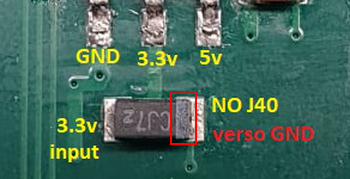
The stripe is on the GND end and the body marking is printed upside-down — consistent with a 180° rotation at assembly. False trails worth keeping: the "IP5306 LX↔VOUT short" was a measurement across inductor L1 (an inductor is a DC short); the "defective AMS1117 batch" was the consequence, not the cause; and the "diode with cathode to chassis" was this capacitor — a tantalum's stripe means plus, the opposite of a diode's band.
Why it happened
The fix was already in the repo: commit dabf830 (2026-04-15) added the
C2 = 180° CPL override for the then-pending order SMT026041362110. Proto #1
was assembled from the pre-fix CPL — the design-side fix existed, the
uploaded files never received it. The same order carried the systemic rotation
error documented in the v4.3.1 batch incident.
Repair
- Desolder C2; the +3V3↔GND short must disappear (the removed part reads shorted out of circuit — definitive proof).
- Do not reuse the tantalum, even if it "recovers".
- Replace with a 22 µF MLCC (≥10 V, X5R/X7R, same 1206 pads). The tantalum existed only for the AMS1117's output-ESR stability window; the current design uses a buck converter, so the constraint is gone.
- Check LED2 — same pre-fix CPL, likely also reversed. Harmless (a reversed LED just stays dark); flip it if the indicator is wanted.
Lessons
- Tantalum stripe = plus — the opposite of the diode convention.
- A shorted regulator is usually the victim. Measure the rail it feeds before replacing it: output ≈ 0 Ω to GND means find the load first.
- A polarity fix is not done until the CPL is re-uploaded. Verify the
uploaded CPL matches
release_jlcpcb/cpl.csvat HEAD on every order. - Photo-verify every part in
POLARITY_AUDIT.mdbefore first power-on — a 30-second check would have saved several regulators.