3D Enclosure Design
Parametric handheld console enclosure designed in OpenSCAD, optimized for FDM 3D printing.
Design Overview
The enclosure follows a landscape form factor inspired by the Game Boy Advance and Nintendo Switch Lite.
Dimensions: 165.8 × 80.8 × 26.6 mm — V3.1 (2026-11-01)
The OpenSCAD project files are in hardware/enclosure/. Open with OpenSCAD 2021.01+ (the Docker image runs the 2026 dev build).
make render-enclosure                # 15 PNG views -> website/static/img/renders/enclosure/
make export-enclosure-stl            # print set -> 3d_case/, viewer set -> 3d_case/viewer/
make generate-enclosure-pcb          # pcb_parts.scad from board.py (also run by generate-pcb)
make verify-enclosure-sync           # scad constants vs board.py / datasheets (34 checks)
make verify-enclosure-requirements   # the user's constraints (20 checks: labels, thin walls, ...)
make verify-enclosure-collision      # CGAL interference: shells vs PCB/panel/battery/caps
make verify-enclosure-stl            # measure the exported STLs themselves (S0-S14)
V3.1 — after printing V3 (2026-11-01)
The printed V3 failed as a case (failure record in the V3 section below): buttons wobbled, parts were misaligned, the L/R mechanism did not work and the power slider broke at once. The user's asks:
| Ask | What changed | Gate |
|---|---|---|
| "The board must sit in a frame, with no ambiguity on its position, so the screw axes are obvious" | Inner wall face 0.3 mm from the PCB edge on every side (pcb_gap); the wall keeps its 2.6 mm, so the outline becomes 165.8 × 80.8 (board + 2 × 2.9) and the corners r 8.9, concentric with the PCB's r 6 (an 11 mm corner would leave 1.7 mm of wall on the diagonal). The 4 corner screws are the only screws | sync body-margin, STL S1 (the 0.3 gap measured on all four sides), R15 |
| "The parts round the edge closer: USB, power switch and micro-SD" | The tighter outline brings the J1 mouth to 3.1 mm inside the face (was 5.2), the SD card end to 2.1 (was 4.2), the SW16 knob to 3.0 (was 5.1) | sync sd-slit, usbc-recess, pwr-window-vs-sw16 |
| "USB: no mouth, only the space of the USB-C — as big as the USB-C — closer, and reinforced (a kind of cage)" | The 17 × 9 recess is gone; the hole is the USB-C plug's own size: shell 8.25 × 2.4 + clearance = 9.0 × 3.2, on the J1 axis, ending at the shell split (the lip above stays whole). The cable's overmold seats on the face: J1's mouth is 3.07 mm inside it, within the 6.5 mm the USB-IF locking-connector spec allows between the receptacle datum and the overmold seat. The 2.6 mm wall round the hole is the collar; inside, a cage round J1 (cradle 0.3 under its body, a 1.2 mm cheek 0.3 off each side; no back wall: J3 and R1/R2 sit behind it). An earlier 13 × 7.1 overmold-sized hole left a 0.05 mm strip of the lip across it, unprintable on the MJP | sync usbc-recess, R13, STL S8 |
| "The power slider broke at once (weak toward the PCB lever) — keep a slider, but reinforced" | A solid shuttle: a 10 mm core slides in a 12 mm window (sill Z 12, open to the split), a 16 mm flange inside keeps it in (1.25 thick beside SW16, a 3.75 thick block under it) (1.2 mm over the wall at full travel; the PCB, 0.2 above, keeps it down), and the knob sits in a 2 mm notch cut through that flange — 7 mm of solid material each side of the knob instead of the V3's two 1.2 mm fork arms. An 8 × 3 nub stands 1.2 proud for the finger | sync pwr-slider-vs-sw16, R8, R13, STL S8, S10 |
| "Pressed, the D-pad goes off axis" | Its pivot ball rested free on the bare PCB. A printed centring cup (Ø6 × 1, 3d_case/dpad_cup.stl) taped to the PCB at the D-pad centre holds the ball in a dimple: the cross still rocks, it can no longer slide. The pivot is 0.45 mm shorter | R18 |
| "Assembly is top shell first, upside down: display, caps, then the PCB — it must sit on the screw axes" | At the PCB plane the top shell is only its outer skin (the lip groove is there), so the board had 1.7 mm of play. Six fences come down from the ceiling to the PCB bottom face 0.1 mm off its edge (+Y at x ±40, −Y at x −15/+30, ±X at y 15, clear of ports, wells and bosses); the bottom shell's lip is notched where they pass | R19 |
| "L and R back to the previous solution" | The V2.1 hinged levers on the back face are back (face 14 × 8, hinge rod printed with the shell, nub on SW11/SW12 at Z 14.3); the back fillet drops to 3 mm so the faces sit on the flat; "L"/"R" engraved beside the levers toward the centre | sync shoulders, lever-counterbore, lever-clear; R14, R15; STL S8, S10 |
| "The caps stay 2 mm out but must have no lateral play, always on axis" | Guide ribs on every face cap but the D-pad (which rocks on its pivot): narrow vertical ribs over the guided length come within btn_rib_gap = 0.05 mm of the bore — tilt 1.6° instead of 6.8°. A negative gap makes them crush ribs | R17 |
| "New battery: the 103665 Li-Po (3.7 V, 3000 mAh, PH2.0) the user bought, on the other side from the speaker grille" | Pocket 70 × 38 × 10 for the 65 × 36 × 10 cell at x 3…73 (away from the speaker), leads out of the −X end toward J3; straps at x 18 / 60, pegged on both sides. A 65 × 40 × 12 cell was tried first: 12 mm reaches Z 14, above the ESP32's underside (12.9) — it does not fit without a deeper bottom shell, which the user ruled out | R10, STL S7; sync battery-pocket against BT1, now the 103665 model (DNK family page in hardware/datasheets/) |
The print set loses lr_cap_x2 and lr_lever_l/r; it gains lever_l.stl /
lever_r.stl and dpad_cup.stl; power_slider.stl is the new reinforced
shuttle. 3d_case/merged.stl is one plate with
every printed part except the two shells (caps, D-pad, Start/Select/Menu,
levers, slider, D-pad cup, two straps), laid out in rows of at most 120 mm
(114 × 99 mm), rebuilt by make export-enclosure-stl
(scripts/build_print_plate.py).
V3.1 design review (2026-11-03)
A review of V3.1 before printing it, against what the gates cannot see (they check the design against the numbers we chose, not whether the numbers are right):
| Problem | Change | Gate |
|---|---|---|
| The six PCB fences were 0.1 mm off the board edge, but JLCPCB routes the outline to ±0.2 mm: a board cut oversize could jam | pcb_fence_gap 0.1 → 0.25 (outline tolerance + 0.05); the M2.5 screws pull the board onto the insert axes | R19 now requires 0.25…0.35; mutation Q33 (0.1) must fail |
| Guide ribs 1.0 mm wide, 0.05 mm off a printed bore: a rib that prints a tenth proud binds and the button sticks pressed | Ribs 0.6 mm wide, so a proud rib shaves in instead of jamming; the gap stays 0.05 (tilt 1.6°, within the 2° asked — 0.1 would rock 3.3°) | R17 |
| The cell had zero room in Z: 10 mm pocket, 10 mm cell, strap on top, 0.9 mm under the ESP32. Pouch cells come a few tenths thick and swell | Pocket floor sunk 0.7 mm into the 2 mm floor (1.3 left under the cell): 10.7 mm floor-to-strap. A 10.0 cell takes a foam pad under it | R10 (headroom ≥ 6 %), R8 (floor ≥ 1.2); mutations Q34, Q35 |
| The caps were exported as they sit in the assembly — on the Ø3 stem with the flange in the air, the D-pad on the tip of its pivot ball (0.2 mm² on the bed). Fine on MJP (wax supports everything), unprintable on FDM, and the opposite of this page's print table | part_*_print selectors turn the eight face caps over about X: the face is on the bed (23 mm² for A/B/X/Y, 113 mm² for the D-pad) | S0 (each print file is a pure rotation of its assembly copy) |
| The plate was one row 252 mm long, past a 220 or 250 mm bed | Shelf packing, rows ≤ 120 mm: 115 × 99 mm | S14 |
| "The buttons must go down straight": the ribs only guided 3.5 mm (front wall + half the well) of an 8.4 mm cap — at a printed 0.15 mm gap it still rocks 4.9° | Piston caps: A/B/X/Y, Start, Select and Menu carry a solid piston (body + 1.2) under the front wall, sliding in a tube that comes down from the ceiling to Z 19.2 (1.6 over the PCB). Guided at the face (front-wall ribs) and at the piston (piston ribs, 0.05 off the tube bore): guide base 6.5 mm, tilt 0.9° nominal, 2.6° at a printed 0.15 gap. The switch is 1.5 tall, so the piston (bottom Z 20.0) stays above it even fully pressed: no hollow needed, and the pills, narrower than the switch, get one too. Stop = a stepped 45° shoulder whose widest step meets the ceiling. Y/Select: piston and tube clipped on the glass side (the tube is a C). Menu: the tube is slotted under LED3-6. D-pad unchanged (it rocks on its pivot) | R17 (tilt ≤ 2° nominal and ≤ 3° at +0.1 print gap; piston stays in the tube and above the switch pressed); mutations Q36, Q37. A PCB respin can do better still: a taller switch with a big plunger the cap fits over |
| Gate S13 sampled the shortened back-right boss rib at 6.1 mm from the axis, past its own 5.0 mm tip: it passed only because the old Menu well filled that point | Sample at the rib's real reach (5.0 − 3.6 = 1.4 from the boss surface, radius 4.3) | S13 |
V3 — the user's review of the V2.1 shell (2026-10-07) — FAILED when printed
V3 was printed (MJP, 0.3 mm) in October 2026 and did not work as an enclosure. It is superseded by V3.1 above; do not print the V3 files. What failed, why, and what replaced it:
| Failure on the print | Cause | V3.1 answer |
|---|---|---|
| Buttons wobbled (V2.1 caps were "perfect") | The only cap change V2.1 → V3 was btn_face_h 0.6 → 2.0: the same well clearance now steers a cap that sticks out 2 mm, so it rocks 6.8° | Guide ribs 0.05 mm off the bore: 1.6° |
| Parts misaligned, the PCB had no defined position | ~1.7 mm of play between board and shell at the PCB plane; nothing located the board on the screw axes | Wall 0.3 mm off the PCB on all sides + six fences 0.1 mm off its edge in the top shell (0.25 since the 2026-11-03 review) |
| L/R bell-crank mechanism did not work | Not diagnosed on the print. The chain cap → bell crank → switch has two pivots and a sliding contact in printed plastic for 0.45 mm of switch travel; the user chose to go back rather than debug it | V2.1 hinged levers on the back face, restored |
| Power slider broke at once | Two 1.2 mm fork arms round the SW16 knob, the weak point toward the PCB lever | Solid shuttle, 7 mm of material each side of the knob |
| D-pad went off axis when pressed | Pivot ball free on the bare PCB | Printed centring cup under the pivot |
| USB-C recess too far from the connector, thin bridge over it | 17 × 9 pocket round a 13 × 6.5 hole, 5.2 mm from J1's mouth | Plug-sized hole 9.0 × 3.2 ending at the split, J1 caged |
The V3 asks below are kept as the record of what was tried.
Five asks, each now a named constant with a gate (R13-R15 in
verify_enclosure_requirements.py, S8/S10 in verify_enclosure_stl.py):
| Ask | What changed | Numbers |
|---|---|---|
| "The buttons must stand about 2 mm out of the face so they can be found by touch, with rounded edges" | btn_face_h 0.6 → 2.0, every cap head rounded with btn_face_r 1.5 (rounded_top_extrude: stacked inward offsets on a quarter circle) | cap 7.9 → 9.3 tall; the stem, flange and well are unchanged |
| "L/R turned 90° toward Z, on the edge between the two covers, 2-3 mm out" — then (2026-10-08) "I keep SW11/SW12 soldered: a printed mechanism from the caps to the switches" | SW11/SW12 stay on the board (TS-1187A, PCB bottom side, actuator facing −Z). A 14 × 8 cap slides through a window in the +Y wall whose top edge is the shell split, 2.5 mm proud; behind it a printed bell-crank lever per side turns the cap's −Y push into a +Z push on the switch | lever pivot: Ø2 pins along X at (y 37.6, Z 13.3) in two U-slot blocks fused to the inner wall; lower arm with a bump 0.05 mm behind the cap flange at Z 7.7; flat upper arm (top Z 14.3 = actuator tip − 0.2) whose end edge sits on the switch centre line. Arms 5.6 / 5.6: cap travel 0.45 and 160 gf, like the face buttons |
| "The speaker on the left" | Player's left = the D-pad side (−X), where board.py also marks SPEAKER_ENC; the battery pocket slides +2.6 mm in X to free the Ø32 seat | grille at (−62.5, 8); pocket x −45…50 |
| "Rounded like the Switch Lite" | Both shells are hulls of fillet slices (filleted_prism / filleted_cavity): plan corners 8 → 11, an 8 mm fillet all round the back face, a 2 mm fillet round the front | the floor's inner outline is inset 8 mm: the speaker driver (edge x −76.5) stays inside it; the front fillet leaves 1.40 mm at the inner corner |
| "The bottom-edge openings recessed into the face: USB ≥ 2 mm, SD ≥ 4 mm, the switch computed so SW16 can really be moved" | USB-C: a 17 × 9 pocket 2 mm deep round the 13 × 6.5 opening, with a 1.6 mm pad on the inner wall face so the floor stays 2.2 thick. SD: the V2.1 16 × 3.5 slit through the bottom-shell wall at Z 14.2 (the V3 20 × 4.7 window was reverted by the user on 2026-10-08); the TF-01A housing front is at | y |
The KSS341GLFS (C&K, C221798 — IP40, 100k, 4 N) is the right on-board side switch for the next PCB respin, with its own footprint at the edge; it cannot sit on the TS-1187A pads (two 1.7 mm feet 7.6 apart, pushing perpendicular to them — the pad pattern's long axis points at the edge). Datasheet kept in hardware/datasheets/SWLR-RESPIN_KSS341GLFS_C221798.pdf.
V2 — what the first printed shell taught us
The V1 shell (printed April 2026) was designed before the panel, the tactile
switches and the JST connector were measured. Everything below is a
consequence of a real dimension, and every dimension is now a named constant
that scripts/verify_enclosure_sync.py checks against board.py or a datasheet.
| V1 problem on the printed shell | Root cause | V2 fix |
|---|---|---|
| Display did not fit / viewport wrong size | V1 viewport was 86.4 × 64.8 (a guessed 4.0" active area). The real ILI9488 3.95" panel with touch is 94.57 × 60.88 × 3.90 mm outline, 83.52 × 55.68 active, with the 8-9 mm driver-ledge border on the D-pad side | Viewport = active area. The glass is centred between the Select cap and the Y cap bodies (0.47 mm gap each side — those two caps have their flange clipped on the glass side); the active area lands at x = 3.7, y = 2. The glass may overhang the FPC slot |
| No room for the FPC tail + extension board | The R37 workaround chain (panel tail → 40P extension board → type-B FFC → slot → J4) runs under the panel, over the PCB | Tail on the D-pad side, U-folded under the glass (1.8 mm fold zone, 2.1 mm from SW4); extension board 28 × 24 × 3 placed under the glass before the slot (x 16.5…44.5); 3.1 mm cable riser → top interior exactly 7.0 mm above the PCB (disp_stack) |
| Nothing held the panel | V1 had a bezel but no frame; the panel floated on the PCB | Top shell grows a display frame: 1.2 mm rim walls from the ceiling down to the PCB along both long sides plus two stubs beside the FFC passage; open on the tail side. The panel is taped to the bezel from inside; the frame contains it and lands on the PCB plane when the screws are tightened |
| No screw bosses in the top shell | V1 screws threaded into the bottom shell's own bosses — the top shell was never fastened | Top-shell bosses Ø7.2 at the 4 PCB corner holes, 7 mm tall (they are the spacer to the PCB), with a socket Ø3.1 × 4.5 for an M2.5 heat-set insert HANGLIFE M2.5 × D3.5 × L4 (OD 3.5, L 4.0) at the PCB end, 2 mm of plastic around it (boss Ø7.2) and a Ø2.8 relief above it (plain cylinders: the insert is pressed from the PCB side and fuses into the boss wall). M2.5 × 20 from the back, through the bottom column and the PCB hole, into the insert |
| Bottom bosses hit the L/R buttons | The corner hole (70, 30.5) is 5 mm from switch SW11/SW12 at (65, 32). A plunger centred on the switch can be at most ~3 mm wide next to the counterbore | L/R are hinged levers: pivot rod printed in the shell at x = 51 (outside the 95 mm battery pocket), nub on the switch at x = 65, face 14 × 8.5 mm ending 0.45 mm before the counterbore. Bottom columns get a Ø4.4 neck under the PCB with a relief on the switch side and four 1.2 mm gussets from the floor (outward and along ±Y, none toward the levers) |
| Button caps could not reach the switches | V1 stems were 2 mm with a 6.4 mm interior; real switch height is 1.5 mm | Cap stack computed from the real numbers (table below): 3 mm guide well under the ceiling, countersunk conical flange, 1.5 mm stem — 7.9 mm total. Sizes up: ABXY Ø9, D-pad arms 6.5, Start/Select 10 × 5, Menu 12 × 4 — Start/Select cannot grow in X and ABXY cannot pass Ø9 without moving a switch (the glass is between them) |
| Battery pocket wrong size and place | V1 pocket 85 × 50 sat over J3 (JST S2B-PH-SM4-TB, 5.5 mm tall under the PCB, datasheet p.4); the fitted cell measures 90 × 50 × 10 (user, 2026-09-16), not 80 | Pocket 95 × 50 × 10 at x −49…46, y −20…30; border 8 mm (below J3's 10.5 mm underside); corners notched for the hinges; clips removed (a pouch cell is held by a foam pad, not pinched). Gates: pocket ≥ measured cell (R10) and clear of all 77 bottom-side parts |
| Speaker grille in the wrong corner | V1 grille bottom-right when looking at the back | Grille top-left when looking at the back = enclosure (+63, +8); driver seat clears the pocket border (x 47.5), the R lever hinge, the side rib and the column (23.6 mm) |
| Only 2 of 6 LEDs visible | LED3-LED6 (bring-up diagnostics) had no light pipes | Ø1.2 light pipes at (54…72, −20.5); where they cross the Menu guide-well ring the ring is opened outward (no web thinner than 1.2 mm) |
| USB-C plug could not seat | Receptacle mouth is at the PCB edge, 5 mm inside the wall; the 9 × 3.2 hole only passed the plug shell | Opening sized for the plug overmold (13 × 6.5), crossing the shell split |
| Battery free to lift against the PCB | Nothing held the cell down; the ESP32 underside is only 0.9 mm above the cell top | Two printed hold-down straps 5 × 1 mm over the cell at x = −30 and +26 (outside the module footprint), pegged into four posts on the pocket border at the cell plane (Z 12); the PCB captures them. Gate: straps and posts ≥ 0.5 mm under every bottom-side part |
| Print service rejected the STLs: "thin walls" | Groove skin 0.7, column necks 0.8, speaker ring 0.7, tongue 1.0, cap flanges 0.8, straps 1.0, lever hook 0.35 | One constant min_wall = 1.2: side walls 2.6 (1.2 skin + 1.2 tongue + 0.2), column contact = outer half-column (no neck), speaker ring 1.7, cap flange 1.2, straps 1.2, lever hook 5 mm wide with 1.35 walls, well rings trimmed through their bore beside the glass, LED pipes open the Menu ring outward, port cutouts only through the wall. Gate R8 tabulates 17 named walls; R12 slices every shell and lever in OpenSCAD, erodes by 0.6 and fails on anything that disappears |
| Bosses and frame 0.4 mm short of the PCB (found 2026-09-17 by measuring the STL) | The lip groove was subtracted as a full slab, chopping the last 0.4 mm off every internal feature — invisible to constant-based gates | Groove is a ring; new gate verify_enclosure_stl slices the exported 3d_case/*.stl with OpenSCAD import() and measures every cutout, boss, pocket and part against board.py, the datasheets and the requirements — a second, independent road (S0–S14) |
| Hand-drawn PCB model | A dozen boxes from memory; J3 was 3 mm too short, LEDs missing | hardware/enclosure/pcb_parts.scad is generated from board.py (all 98 fitted parts with body sizes/heights, slot, holes); a stale file is a red gate |
| Engraved labels wrong | V2.0 mirrored the whole label group about x = 0 (A/B/X/Y landed on the D-pad); V2.1 mirrored every top glyph (backwards B, STA/SEL) | Top-shell glyphs are engraved as-is (read from the front), only the back-face L/R are mirrored about their own centre; gate R9 exports the glyphs and checks position and chirality (stem side of the B and the L) |
Z-axis stack (closed assembly, Z = 0 at the back face)
| Z (mm) | What |
|---|---|
| 0 | Back face |
| 2 | Floor inner face — battery pocket, speaker seat, L/R lever pivot blocks |
| 13.3 | L/R lever pivot axis (pin Ø2, top flush with the lever top plane Z 14.3); cap window Z 8 – 16, cap axis Z 12 |
| 2 – 12 | Battery cell (90 × 50 × 10, measured) |
| 10.5 – 16 | J3 JST (5.5 mm under the PCB) — the pocket never overlaps it in XY |
| 12.9 – 16 | ESP32 module (3.1 mm), 0.9 mm above the cell |
| 16 | PCB bottom face = shell split = bottom column tops (pcb_z) |
| 17.6 | PCB top face; face switches to 19.1 (TS-1187A code A, 1.5 mm) |
| 17.6 – 20.7 | Cable riser (3.1): folded tail, extension board, type-B FFC |
| 20.7 – 24.6 | Panel (3.9 mm, touch version) |
| 24.6 | Ceiling (front wall inner face) = glass top |
| 26.6 | Front face |
Button caps — computed from the stack
All face caps share one stack; the numbers are echo()ed by OpenSCAD on every render and checked by the sync gate (cap-stem).
| Element | Height | Constant |
|---|---|---|
| Face proud of the front surface | 2.0 (rounded, r 1.5) | btn_face_h, btn_face_r |
| Body through the wall | 2.0 | wall |
| Body through the guide well under the ceiling | 3.0 | btn_guide_h |
| Flange plate (outside the well bore) | 1.2 | btn_flange_h |
| Stem to the switch actuator | 1.1 | btn_stem_h = 7.0 − 3.0 − 1.2 − 1.5 − 0.2 |
| Total cap height | 9.3 | btn_cap_h |
That stack is now the D-pad's only. A/B/X/Y, Start, Select and Menu are piston caps (2026-11-03), same 9.3 total:
| Element | Z | Constant |
|---|---|---|
| Face top | 28.6 | btn_face_h above the front face |
| Body through the front wall (ribs 0.05 off the hole) | 24.6 – 26.6 | wall |
| Stepped 45° shoulder, widest step meets the ceiling (stop) | 23.64 – 24.84 | z_shoulder0, btn_piston_steps |
| Piston, body + 1.2, ribs 0.05 off the tube bore | 20.0 – 23.64 | z_piston0, btn_piston_extra |
| Stem Ø3 to the plunger (0.2 pre-travel) | 19.3 – 20.0 | btn_piston_stem_h |
| Tube in the top shell, bore = piston + 0.3, wall 1.2 | 19.2 – 24.6 | guide_tube(), z_tube0, btn_tube_t |
- Cap body = cutout outline − 0.6 mm (0.3 per side). Flange = body + 1.2 mm radial, 1.2 mm plate; its top 1.5 mm is a stepped 45° cone that seats in a matching countersink at the well's end — self-centring and printable face-down without supports.
- Stem Ø3.0 (switch plunger Ø2.0). 0.2 mm pre-travel gap, 0.25 mm switch travel.
- The D-pad additionally has a Ø3 centre pivot resting on the PCB (3.2 mm tall) so the cross rocks instead of sinking.
- Guide ribs (V3.1, piston since 2026-11-03 — see the table above; the text below is the V3.1 record): every face cap but the D-pad carries narrow vertical ribs (1.0 wide, 0.6 since the 2026-11-03 review; ABXY at 45°/135°, the pills on both long sides at ±w/4 and on both ends) over the guided length — from above the countersink to the front face, 3.5 mm. They stop
btn_rib_gap= 0.05 mm from the bore, so a cap can tilt 1.6° instead of 6.8° on its 0.3 mm/side body clearance. Set the gap to 0 or below for crush ribs. The D-pad has none: it must rock on its pivot. - L/R levers (V3.1, the V2.1 design): one hinged lever per side on the back face (L is the mirror of R, so two files). Face 14 × 8 standing 1 mm out of the back through a 14.8 × 8.8 cutout, a 1.2 mm flange inside the floor (1 mm wider), a Ø3.4 nub up to Z 14.3 (actuator tip − 0.2) on SW11/SW12 at (±65, 32), a 5 mm tongue hooking over a Ø2 rod printed with the shell at x = ±50.4. Prints face-down as it sits:
3d_case/lever_l.stl,3d_case/lever_r.stl. - Power slider (V3.1, reinforced): core 10 wide through a 12 mm window at x = −40 (sill Z 12, open to the split), flange 16 wide behind the wall (1.25 beside SW16, 3.75 under it) with a 2 mm notch for the MSK12C02 knob (1.6 wide, 1.6 travel, 3.0 mm inside the face), nub 8 × 3 × 1.2 proud.
3d_case/power_slider.stl, printed on the lower block's inner face, nub up. - Brand lines (2026-10-08): "GAME BRO!" engraved 0.6 deep above the screen on the top cover (4.5 mm, y = 36.3) and "CPJ & CP 2026" low on the back face (3 mm, y = −27, mirrored for reading from the back); gate R9 counts their glyphs and checks the chirality of the B and the J.
Screws and inserts
- 4 × M2.5 heat-set inserts HANGLIFE M2.5 × D3.5 × L4 (OD 3.5, L 4.0), pressed into the top bosses from the PCB side (socket Ø3.1 × 4.5; boss Ø7.2 = 2.05 mm wall).
- 4 × M2.5 × 20 pan head from the back, counterbore Ø5.0 × 1.8. Path: floor → bottom column (Ø6, Ø2.8 bore, outer half-column for the last 2 mm so the contact face clears SW11/SW12, four 1.5 mm gussets) → PCB Ø2.5 hole → insert (Z 17.6…21.6) → tip at Z 21.8, 0.2 mm into the Ø2.8 relief (Z 22.1…24.1). A 25 mm screw would hit the roof: the gate
R6 screw-lengthrejects it. - The two centre PCB holes (±25, 0) are under the battery pocket and stay unused.
Rendered Views
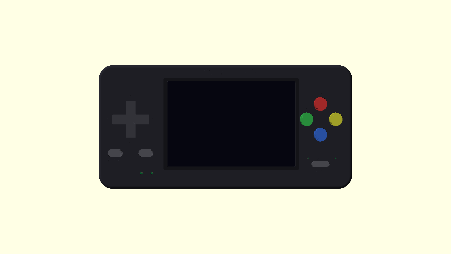
Front (Display Side)
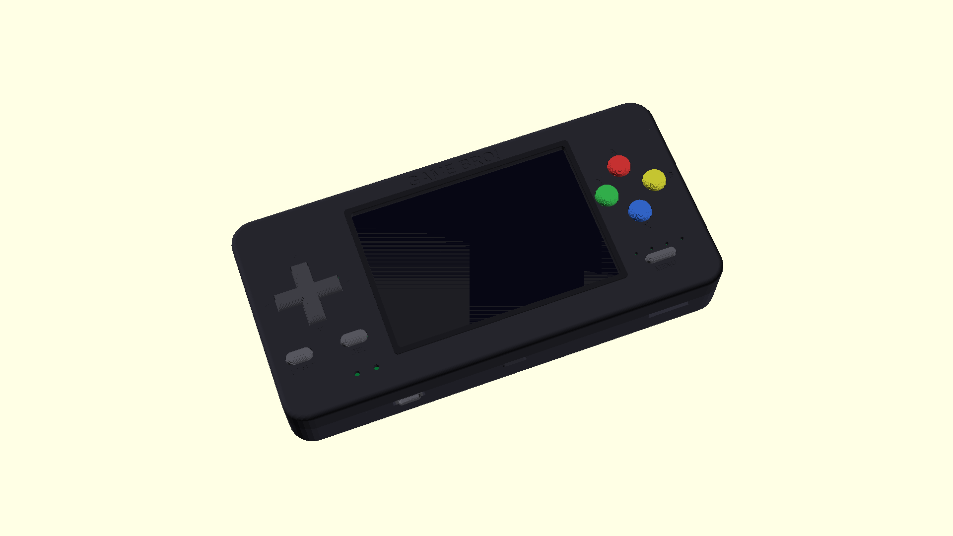
Plan view
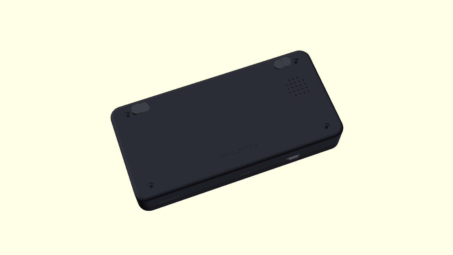
Back — 3 mm fillet, L/R lever faces, speaker grille (player's left), screw counterbores
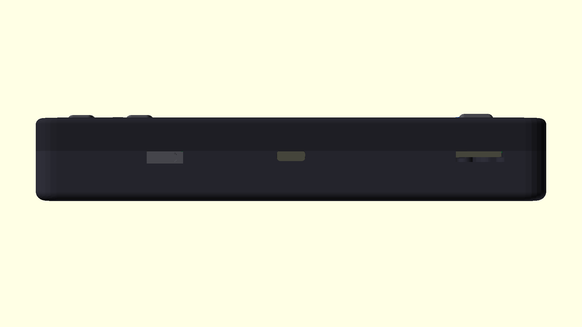
Bottom edge — USB-C overmold opening (no recess), SD slit, power-switch window in its trough
L/R lever (R side) cut through SW12 — face in the back, hinge rod, nub under the switch

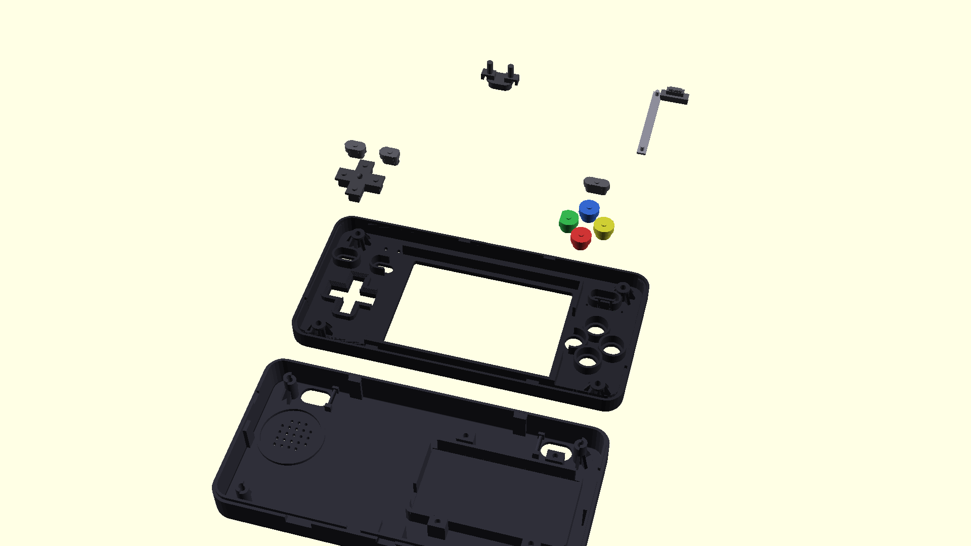
Every printed part, as it comes off the bed
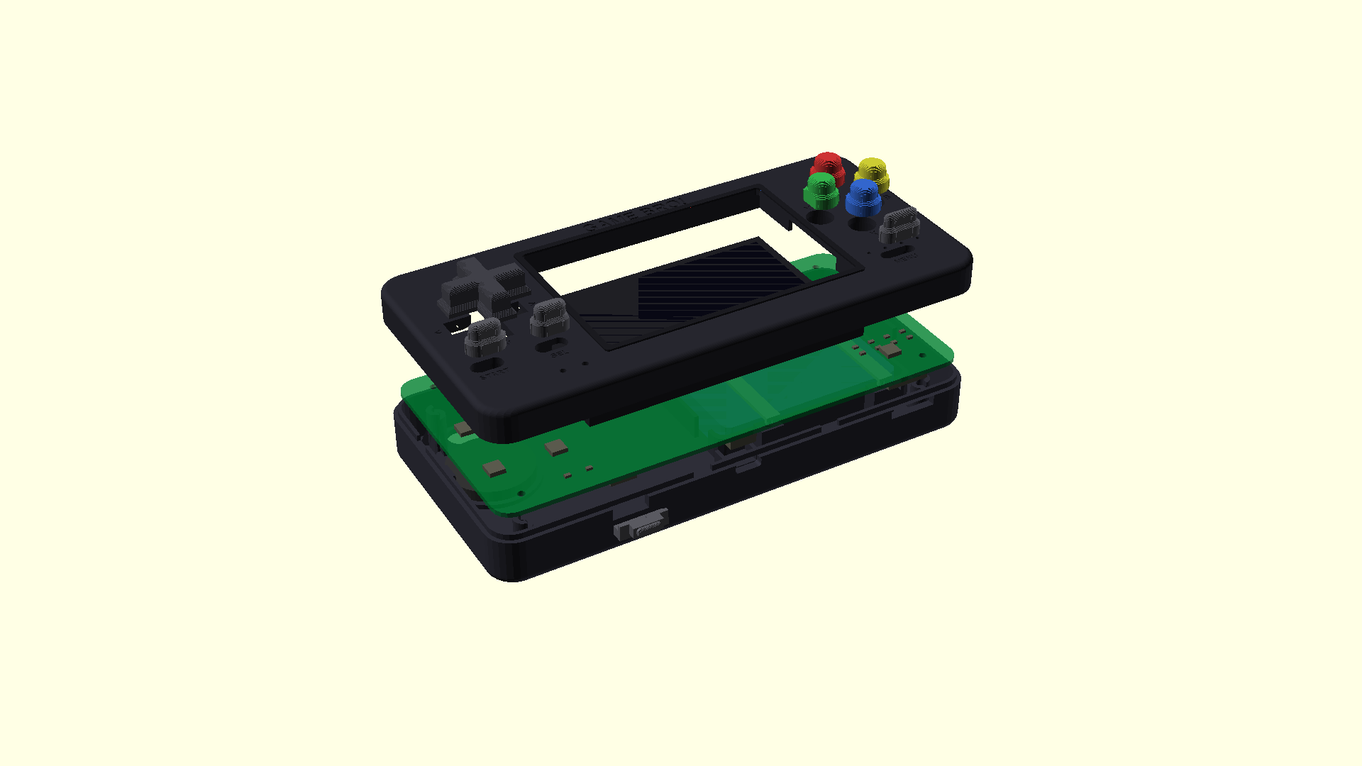
Exploded View
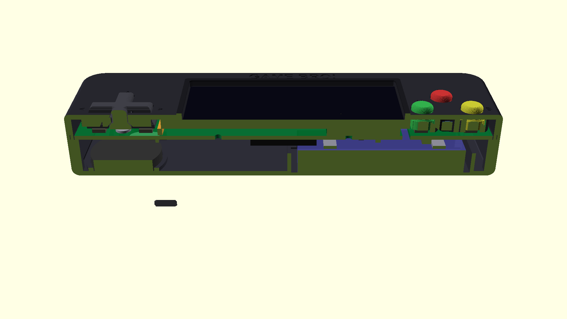
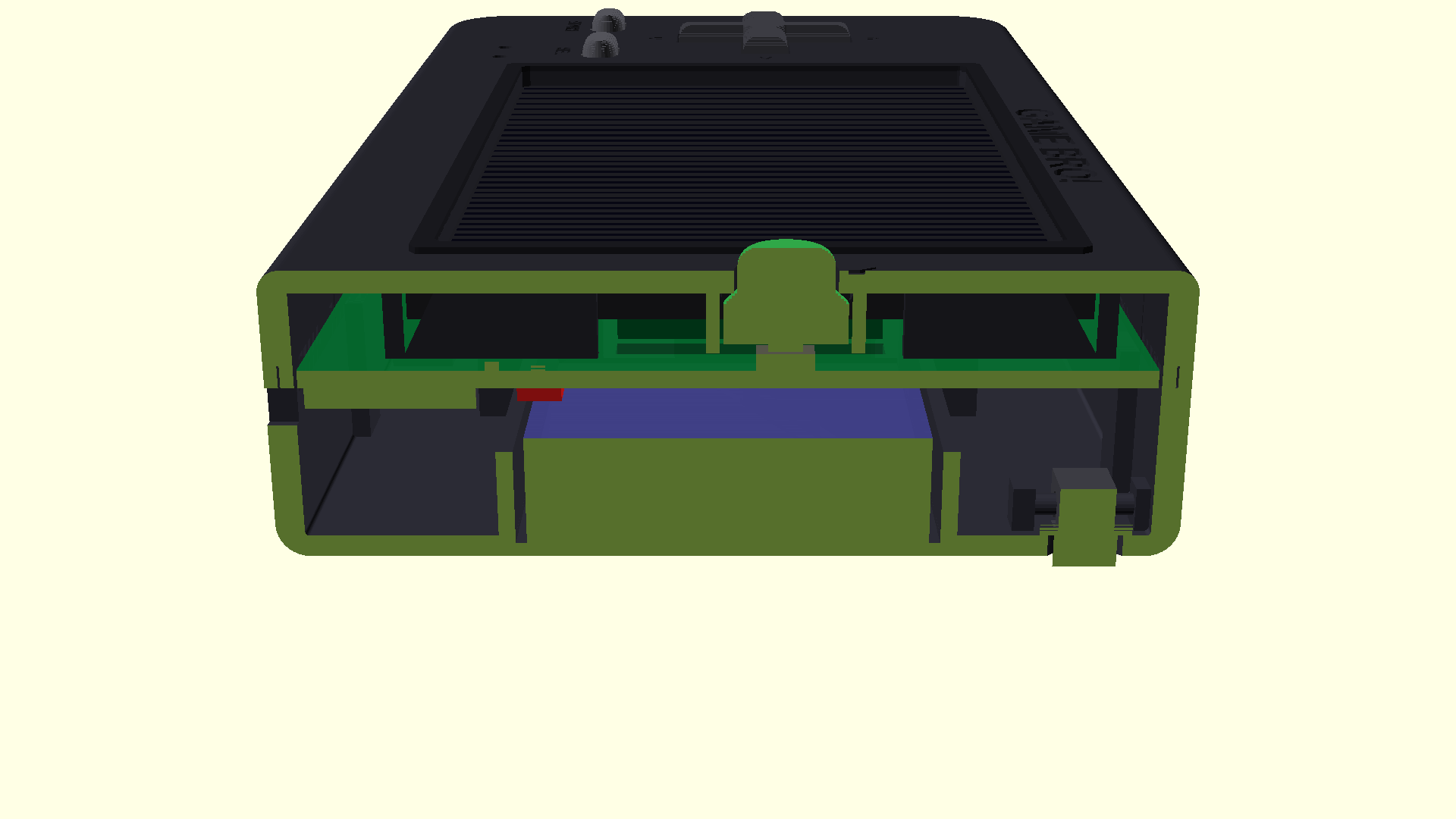
Cross-section, XZ at Y = 0 — battery, module, PCB, panel + riser, caps
Cross-section, YZ through the Y button — panel pocket, tail fold, guide well
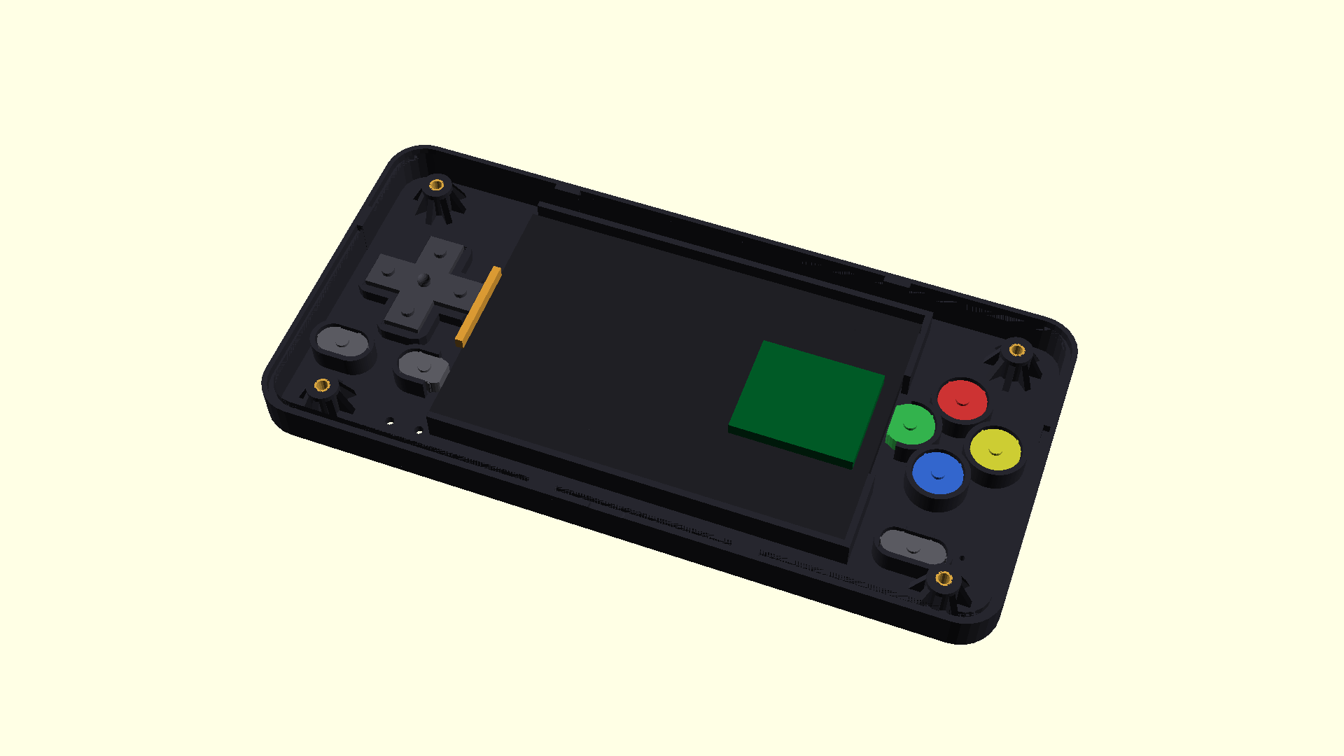
Top shell from the inside — display frame, screw bosses, guide wells
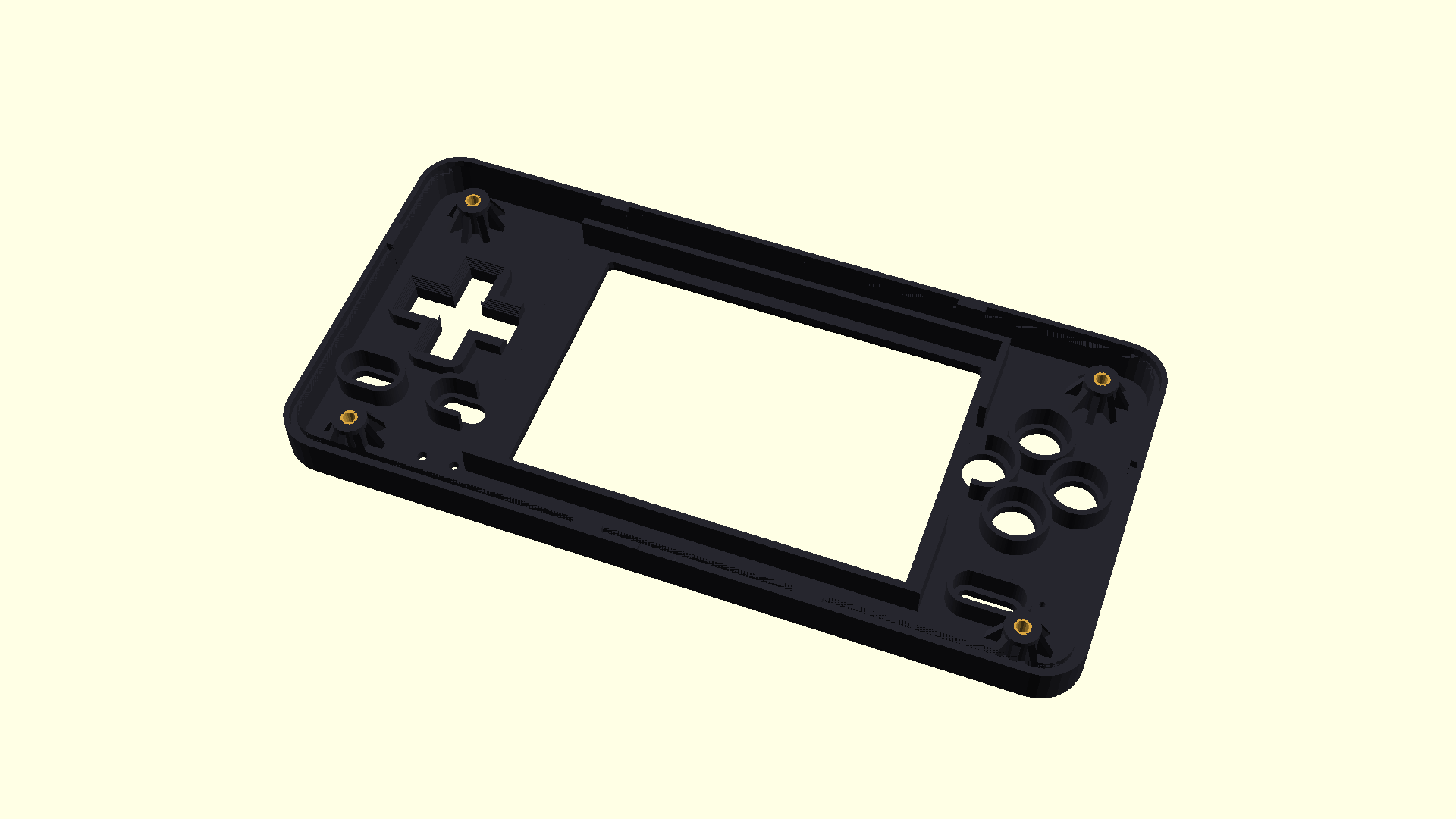
Same, bare — bosses with the four inserts seated, LED light pipes through the Menu well
The groove bug the STL audit caught (section through a boss, before / after)
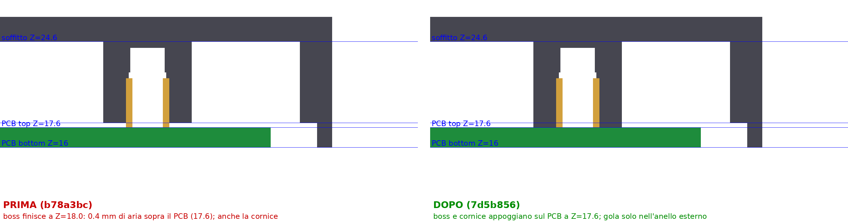
Exact 2D sections at y = 30.5 (through the top-right boss), old model on the left. The lip groove was subtracted as a full 167.6 × 82.6 slab from Z 18.0 up: every boss and frame wall stopped at Z 18.0, 0.4 mm above the PCB top (17.6), and the insert stuck out of its socket. The constants said "7.0 mm interior"; only measuring the exported STL (gate S5) showed the geometry did not. The groove is now the ring between the outer skin and the interior.
One boss cut through its axis — the print geometry of the insert socket

From the PCB-side face of the boss inward: socket Ø3.1 × 4.5 deep for the insert (HANGLIFE M2.5 × D3.5 × L4: OD 3.5, L 4.0, knurled — pressed with a soldering iron, flush with the boss face), then a Ø2.8 relief 2.0 deep for the screw tip, then 0.5 mm of boss plus the 2 mm front wall. Boss Ø7.2 = 2.05 mm of plastic around the socket (the user asked for 2). M2.5 × 20 tip at Z 21.8 = 0.2 mm past the insert end: full 4 mm engagement. Gate R6 pins these numbers.
Bottom shell without the PCB — 103665 pocket with hold-down straps, columns with gussets, ribs, L/R levers on their hinges, USB cradle, speaker seat ring
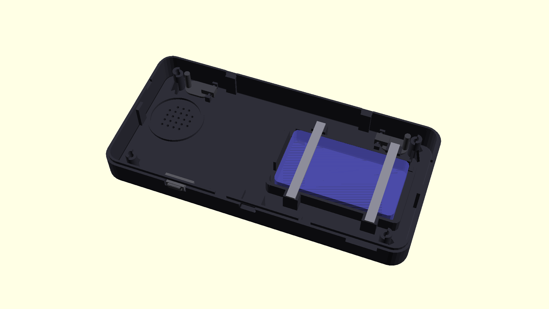
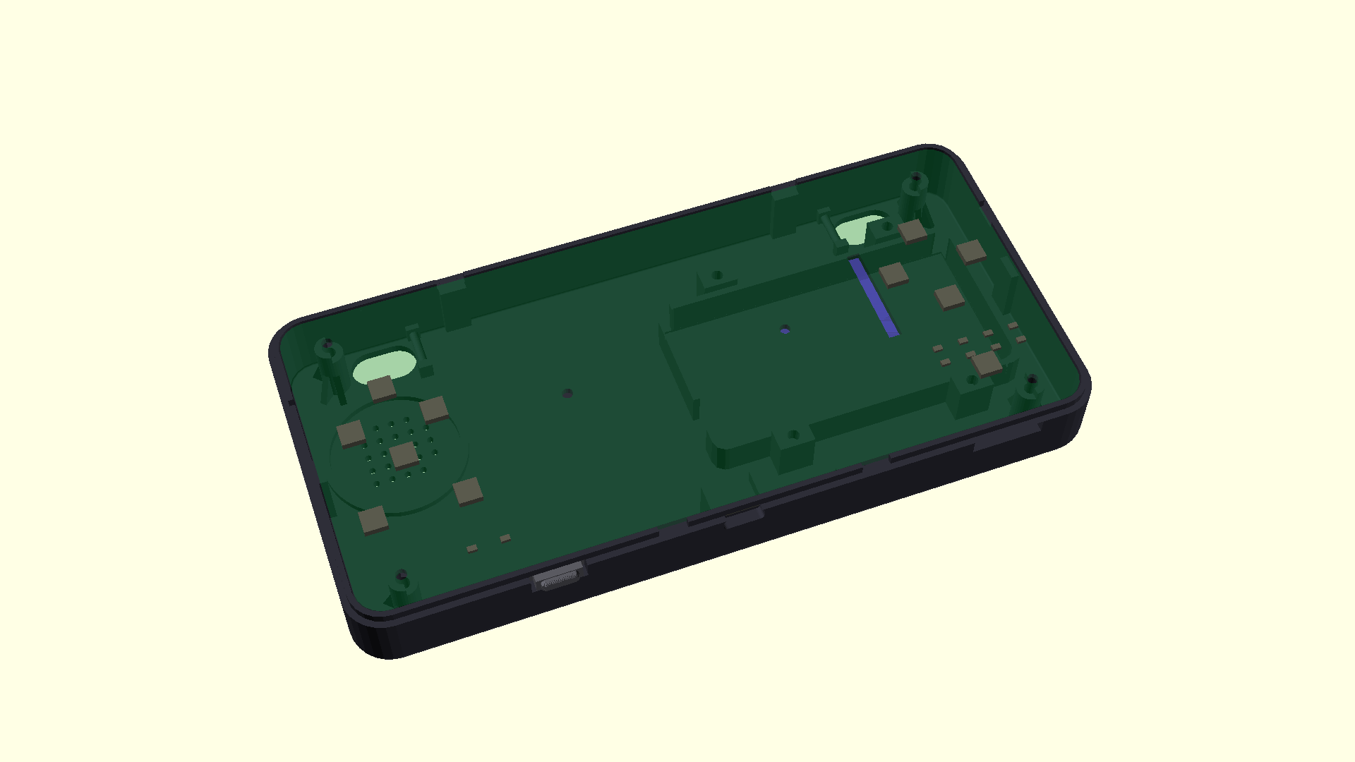
Fit Check (bottom shell + PCB + battery + L/R levers)
Interactive 3D Viewer
Open the interactive 3D viewer — three views: Assembly, Exploded, and Parts, which lays every piece out side by side as it sits on the print bed (the inner ones too: L/R levers, power slider, D-pad cup, straps). Each part in the list has a show/hide box and a Solo button that shows only that part and frames it; Show all brings everything back. The viewer loads the print files themselves (3d_case/*.stl, served through staticDirectories) and only rotates and moves them into place (3d_case/viewer/placement.json), so what you see is exactly what you print. Only the display and the PCB, which are not printed, come from 3d_case/viewer/parts/. make export-enclosure-stl regenerates everything; gate S0 of verify_enclosure_stl.py proves each placed print file lands exactly on the design's assembly position with a pure rotation (never a mirror). No STL lives under website/.
The Parts & colours panel lists every placed part. A colour picker repaints it live, a checkbox hides it, and clicking a part in the 3D view selects its row. Colours are kept in the browser (localStorage) and survive the Assembly/Exploded switch. Copy puts the whole colour set on the clipboard as JSON and Paste applies one. The print files are never touched.
Features
Front Panel (top shell)
- Display viewport 83.52 × 55.68 (+0.3 clearance) at (3.7, 2) — the panel's active area, cosmetic 2 mm raised bezel; glass pocket x −46.8…48.3
- Display frame — rim walls to the PCB plane along both long sides (starting 1.5 mm in from the tail edge, clear of LED2) and two stubs beside the FFC passage on the ABXY side; open on the D-pad side where the tail U-folds
- D-pad 24 × 6.5, A/B/X/Y Ø9 (offsets follow the board's DFM shift: Y at −9), Start/Select 10 × 5, Menu 12 × 3.8 — every cutout has a 3 mm guide well with a countersunk flange seat
- LED light pipes Ø2 at (−55, −30), (−48, −30); Ø1.2 at (54/60/66/72, −20.5)
- 4 screw bosses Ø7 with M2.5 insert sockets at the PCB corner holes
Back Panel (bottom shell)
- 3 mm fillet all round the back face, 8.9 mm plan corners (V3.1, concentric with the PCB's)
- L/R lever faces 14 × 8 at (±58.8, 32) in 14.8 × 8.8 cutouts; "L"/"R" engraved beside them at (±47.8, 32)
- Speaker grille — Ø22 hole pattern at (−62.5, 8), seat ring Ø32 for the 28 mm driver (player's left, the D-pad side)
- 4 × M2.5 counterbores Ø5 at (±70, ±30.5)
Bottom Edge
- USB-C 9.0 × 3.2 hole — the plug's own size — at Z 12.8…16.0 on the J1 axis, straight through the 2.6 mm wall, no recess (V3.1); J1's mouth 3.1 mm inside the face
- SD card slit 16 × 3.5 centred at Z = 14.2, x = 60, bottom shell only (the V2.1 slit; the card end is 2.1 mm inside the face); no guide shelf any more — the wall is at the PCB edge
- Power slider window 12 mm wide at x = −40, sill Z 12, open to the split; the reinforced shuttle carries the knob (3.0 mm inside the face) out to a nub 1.2 proud
Internal (bottom shell)
- Battery pocket 70 × 37 (the user's 103665 cell 65 × 36 × 10, +5 lead clearance) with an 8 mm border, centred at (0, 0), lead notch on +X at y = −10
- L/R lever hinges at x = ±50.4: two 3 × 2 blocks per side at y 25.5…27.5 and 36.5…38.5, a Ø2 rod at Z 4 printed with the shell
- USB-C cradle 9.6 × 6.5 on the floor under J1, top 0.3 mm under its body
- Battery hold-down — 4 posts 8 × 3 × 10 on the outer face of the ±Y border walls with Ø2.7 peg holes; 2 printed straps 5 × 1 × 59 mm with Ø2.4 pegs (
3d_case/battery_strap_x2.stl, print 2) - Column gussets — 4 per bottom column, 1.2 × 6 × 8 mm
- PCB edge ribs — 6 blocks under the PCB edge (±40 top, ±25 bottom, ±80 sides) so the board cannot flex under the D-pad
- Speaker seat
Physical Layout
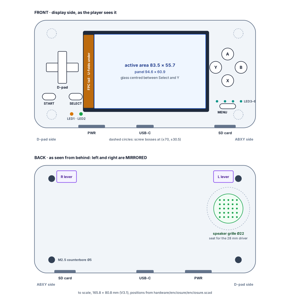
The FRONT view is what the player sees; the BACK view is what you see when you physically turn the device around, so left/right are mirrored. USB-C, the SD slot and the power switch are on the bottom side of the PCB; in device terms SD is on the ABXY side, the power switch and speaker on the D-pad side.
Dimensions Reference
| Element | Dimension | Notes |
|---|---|---|
| Overall body | 165.8 × 80.8 × 26.6 mm | PCB + 2 × (0.3 gap + 2.6 wall); 26.6: the 7.0 mm display stack |
| Wall thickness | floor/front 2.0, side walls 2.6 | side = 1.2 skin + 1.2 lip + 0.2 clearance |
| Corner radius | 8.9 mm plan (PCB r 6 + 2.9); back fillet 3, front fillet 2 | V3.1 |
| Panel outline pocket | 94.57 × 60.88 + 0.3/side | glass centred at x = 0.75 between the Select and Y caps; tail border 8.5 on the D-pad side (user: 8-9 mm) |
| Display viewport | 83.52 × 55.68 + 0.3/side | active area at (3.7, 2); r 1.0 corners |
| Cable riser under the panel | 3.1 mm | disp_riser |
| D-pad cutout | 24 × 6.5 cross | stems at r 9 = board DPAD_OFFSETS |
| Face button holes | Ø9 | A/B/X/Y at board ABXY_OFFSETS; Y flange clipped on the glass side |
| Start/Select | 10 × 5 pills | Select flange clipped on the glass side |
| Menu | 12 × 3.8 pill | 1.2 mm web to the LED4/LED5 light pipes |
| L/R lever | face 14 × 8, 1 mm proud of the back | hinge rod x = ±50.4; nub Ø3.4 to Z 14.3 on SW11/SW12 at (±65, 32) |
| USB-C opening | 9.0 × 3.2, no recess | the plug shell 8.25 × 2.4 + clearance, Z 12.8–16.0 |
| SD slit | 16 × 3.5 (Z 12.5…16.0, open to the split) | bottom shell only; card end 2.1 inside the face |
| Power slider | core 10, window 12 (sill Z 12), flange 16 (1.25 / 3.75), notch 2, nub 8 × 3 × 1.2 | x = −40; knob travel 1.6 |
| Battery pocket | 70 × 38 × 10.7 | 103665 cell 65 × 36 × 10 + 5 mm leads; floor sunk 0.7 (1.3 left), border 1.5 × 8 tall; centre (38, 0) |
| Battery straps | 2 × (5 × 1.2 × 61.4) | at x = −30 / +26, Z 12…13.2; posts 8 × 5.2 × 10 |
| Bottom column | Ø6 / Ø2.8, outer half-column for the last 2 mm, 4 gussets 1.5 | 13.4 mm tall |
| Top boss | Ø7.2, insert socket Ø3.1 × 4.5 + relief Ø2.8 × 2.0 | 7 mm tall, plain cylinder, 2 mm wall |
| Speaker | grille Ø22 at (−62.5, 8), seat ring Ø32 / Ø28.6 | 28 mm driver, 5 mm thick |
Printing
| Part | Selector | Print file | Orientation |
|---|---|---|---|
| Top shell | case_top_print | 3d_case/case_top.stl | front face down (bosses, frame and wells grow upward — no supports) |
| Bottom shell | case_bottom | 3d_case/case_bottom.stl | back face down; the 3 mm back fillet prints as a shallow overhang |
| D-pad, A/B/X/Y, Start/Select/Menu | part_*_print | 3d_case/*.stl | face down (turned over about X); the conical flange grows upward, no supports; on FDM use a brim on Start/Select/Menu (small flat on the bed) |
| L/R levers (L and R, mirrored) | part_shoulder_l, part_shoulder_r | 3d_case/lever_l.stl, 3d_case/lever_r.stl | face down, as in the assembly |
| Power slider | part_power_slider_print | 3d_case/power_slider.stl | lower block's inner face down, nub up |
| Plate: every part but the two shells | — | 3d_case/merged.stl | one bed 114 × 99 mm, built from the files above |
| Battery straps (×2) | part_strap_print | 3d_case/battery_strap_x2.stl | flat, pegs up |
| Parameter | Value |
|---|---|
| Material | PLA or PETG (caps in PETG or TPU feel better) |
| Layer height | 0.2 mm shells, 0.12 mm caps |
| Infill | 20 % shells, 100 % caps and slider |
| Supports | none |
| Tolerances built in | 0.3 mm per side on caps and the panel pocket, 0.3 mm on the alignment lip |
Assembly order
The top shell goes first, upside down; the PCB finds its position in it against the six fences, with its corner holes on the inserts.
- Press the 4 M2.5 inserts (D3.5 × L4) into the top bosses (from the PCB side, soldering iron ~200 °C, flush with the boss face).
- Tape the panel to the bezel from inside the top shell (glass against the ceiling), tail on the D-pad side.
- Drop the face caps into their tubes from inside, face first, until the shoulder meets the ceiling (the D-pad: flange cone into its well's countersink). Seat the D-pad centring cup on the D-pad's pivot ball, dimple down, with a piece of double-sided tape on its flat top: when the PCB goes in (step 3) the cup sticks to it at exactly the pivot's position, no measuring. If the D-pad still walks off axis on the print, the clean fix is an NPTH under the pivot at the next PCB respin, and the cup goes away.
- Push each L/R lever's face out through its cutout in the back and hook its tongue over the hinge rod (flange inside the floor); drop the power slider into its window from inside (nub out, notch up, centred); seat the speaker in its ring; cell in the pocket, leads through the +X notch to J3; drop the two straps' pegs into the post holes.
- PCB onto the columns and ribs; fold the tail under the glass into the extension board (left of the slot), FFC through the slot into J4.
- Close and drive the 4 × M2.5 screws from the back.
Customization
All dimensions are parameterized in enclosure.scad; every column-0 constant is part of the sync-gate contract (numbers, names and + - * / only).
disp_border_tail = 8.5;  // measure the panel's driver-ledge border and set it
disp_riser = 3.1;        // cable space under the glass
bat_w = 90; bat_h = 50; bat_d = 10;   // cell L x W x T (measured) — another cell: change these + R10
bat_offset_x = 2.6; bat_offset_y = 5;
Run the three gates after any change:
| Gate | What it proves | Checks |
|---|---|---|
verify_enclosure_sync | the scad agrees with board.py (positions, holes, panel spec, all 98 parts) and the datasheets (switch incl. the TS-1187A cover and actuator, JST, ESP32, cell, MSK12C02, TF-01A); straps/posts and the L/R levers and pivot blocks clear every bottom part; the levers' arm on SW11/SW12, 5.6 / 5.6 arms, swing under the cover, pin held in its slot; slider, SD slit and USB-C recess vs the board | 33 + 21 mutations |
verify_enclosure_requirements | the model still does what was asked: 7.0 mm stack, glass between the caps, tail/extension zones, 6 LEDs, speaker side, insert/screw geometry, button sizes, 24 named minimum thicknesses, the measured 90 × 50 × 10 cell, the hold-down straps, engraved labels beside their own button and not mirrored, a measured thin-wall audit (OpenSCAD slices eroded by 0.6 mm), and the V3 asks: edge recesses, proud rounded caps, rounded shell | 19 + 23 mutations |
verify_enclosure_collision | the shells share no volume with the PCB parts, panel stack, battery, speaker or caps; caps vs panel; panel vs PCB parts (OpenSCAD CGAL) | — |
| verify_enclosure_stl | the other road: no scad constants — it slices 3d_case/case_top.stl, case_bottom.stl, the L/R caps and levers, the slider and the viewer parts with OpenSCAD import() and measures envelopes, every front cutout vs its switch/LED placement, the viewport vs the panel datasheet, the glass pocket and its gaps, insert sockets (Ø3.1 × 4.5, 2 mm wall), counterbores/bores/half-columns, pocket vs the measured cell and J3, the edge openings (L/R windows, slider slot, USB-C recess depth, SD slit width), grille side, cap/edge-part/strap/display alignment and thin walls on the STL slices; refuses STLs older than the scad | 11 |
All four run in make verify-all; make dispatch routes a red one to the cad-engineer agent. make export-enclosure-stl ends with the collision gate and the STL audit.
Modular Design
| File | Contents |
|---|---|
enclosure.scad | Constants contract, filleted top/bottom shells, face caps, L/R caps and levers, power slider, lever pivot blocks, views, collision_check, labels_check |
pcb_parts.scad | Generated by scripts/generate_enclosure_pcb.py from board.py — outline, slot, holes, 98 parts with body L × W × H |
modules/buttons.scad | 2D cutout shapes, guide wells with countersink, conical cap flanges |
modules/display.scad | Viewport cutout and bezel |
modules/ports.scad | USB-C, SD card, power switch, speaker grille cutouts |
modules/battery.scad | Battery compartment primitives |